Background
Batteries
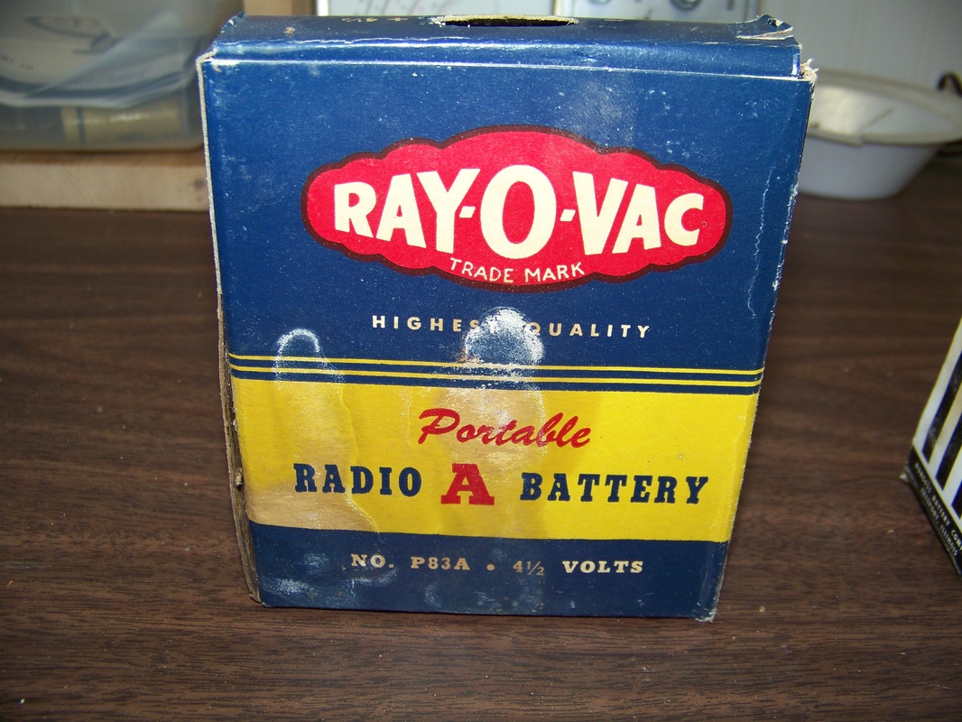
Pictured below are examples of an "A" and "B" battery I just pulled out of my 1947 TRAV-LER Model 5020 portable vacuum tube radio that I am in the process of restoring. Two "A" 4.5 Volt batteries were connected in series to provide the required 9 Volts for the tube filaments. In addition, two "B" 45 Volt batteries are connected in series to provide the required 90 Volt plate voltage. No "C" battery is required as the Model 5020 uses grid leak resistors to provide required voltage.
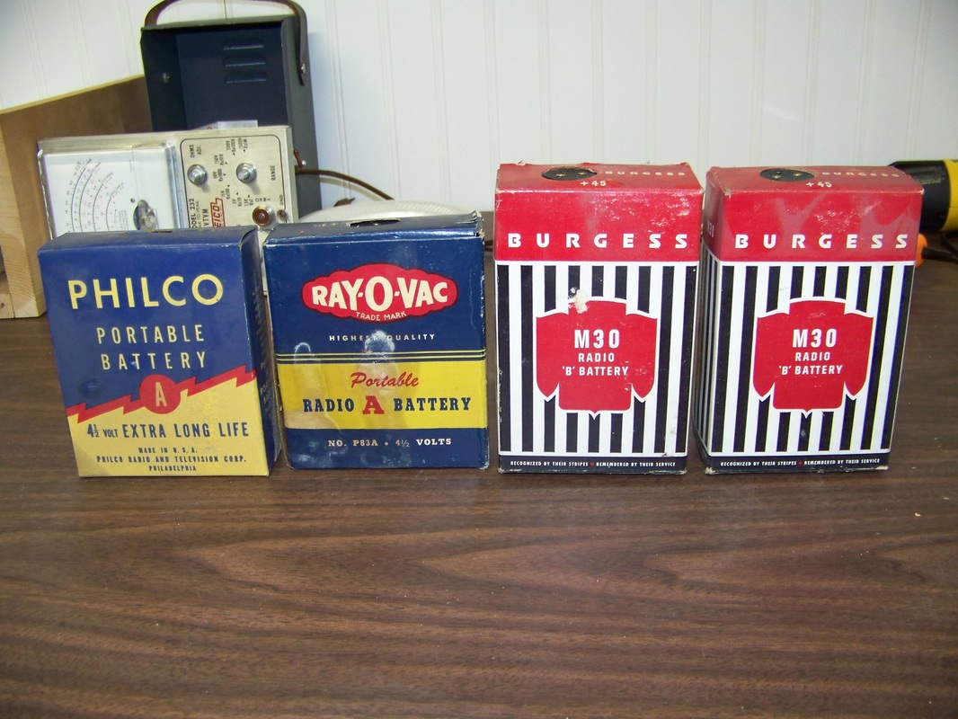
In the early days of electronics, vacuum tube devices were powered by batteries as many homes had not been wired for electricity. The batteries used for powering these early electronic vacuum tube devices were classified as "A", "B", and "C" batteries.
The "A" battery was used to provide power to the filament of a vacuum tubes in the device. Typically this battery was low voltage (usually between 2 to 7.5 volts) but required a high amperage to power the vacuum tube filaments. Lead-acid types, like classic car batteries, were used initially until better high amp-hour Zinc-Carbon batteries were developed. The "B" battery was used to provide the plate voltage of a vacuum tube. These were typically of Zinc-Carbon variety with many cells wired in series to provide the low amperage and high voltage (usually 22.5, 45 or 90 Volts) required. The "C" battery was used to provide bias to the control grid of a vacuum tubes. This was typically a low voltage and low amperage (9 Volts with several 1.5 Volt taps) Zinc-Carbon battery. The C battery was largely done away with as it was soon discovered that the needed voltage/current bias could be derived from the "A" battery using a grid leak resistor or voltage divider biasing. I plan on gutting these vintage "A" and "B" batteries, then installing modern batteries wired in the proper fashion to achieve the proper voltage/current required. Step 1 Chassis Removal
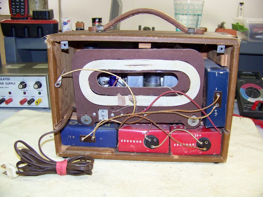
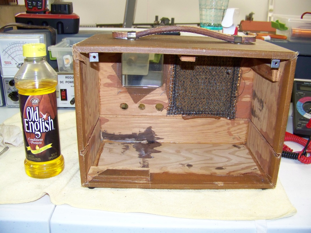
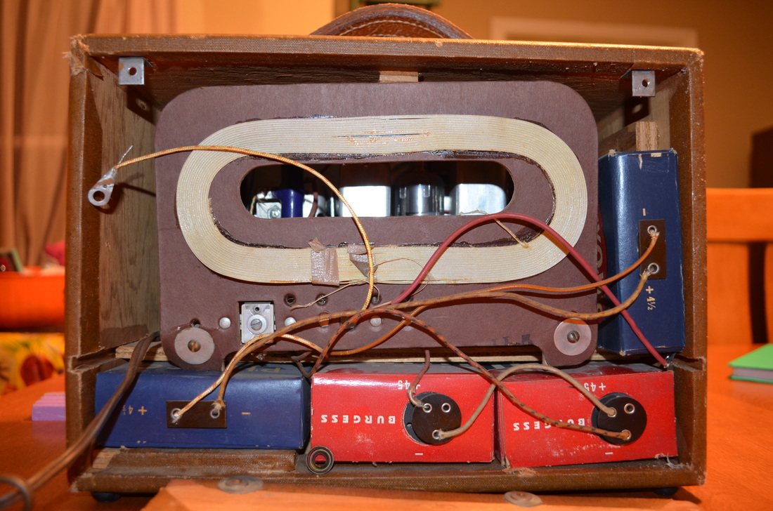
Here is the back view of the Model 5020, with the back cover and batteries removed.
As in most vintage radios, all of the electronic components are attached to a metal enclosure called a "chassis". In the Model 5020, the chassis is behind the internal antenna mounted on a cardboard form. That chassis is attached to a wooden shelf in the Model 5020's enclosure. The wooden self allows the 45 Volt batteries to be housed under the chassis for operation under battery power. 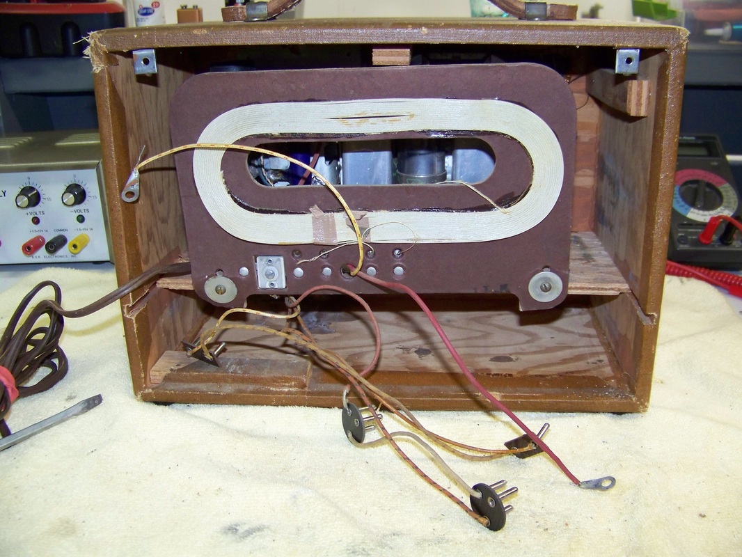
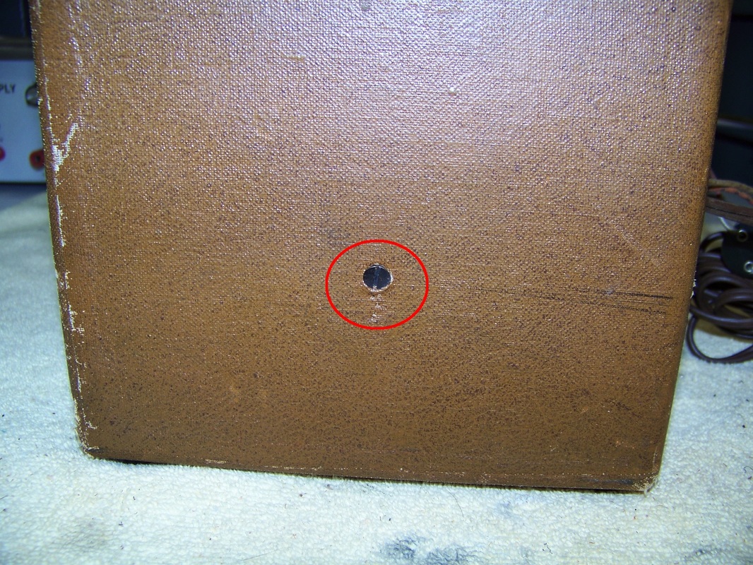
In order to remove the shelf that the Model 5020's chassis is attached to, you have to remove one screw from each side of the cabinet.
You must remove the knobs located on the front of the Model 5020 enclosure before you can slide the chassis out the back. The tuner and the power selector switch pull off while the volume knob is held in place with a set screw.

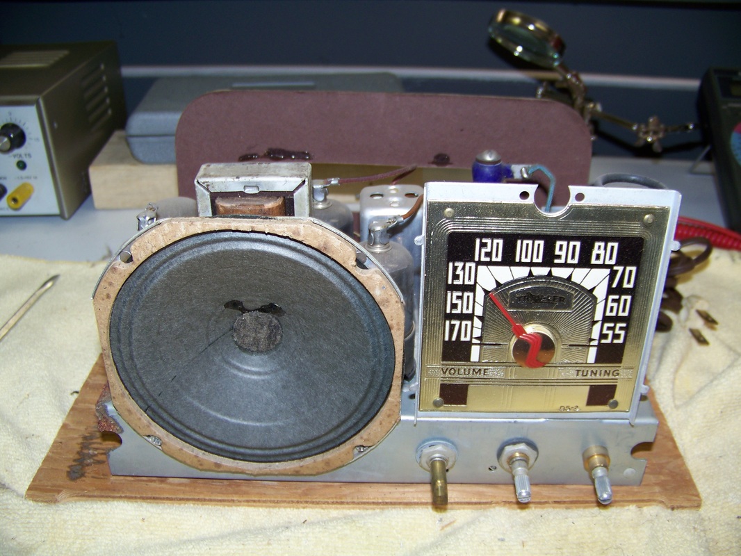
Once the knobs have been removed, you can slid the shelf with chassis attached, out the back. Here is a picture of the chassis and shelf removed from the Model 5020's cabinet.
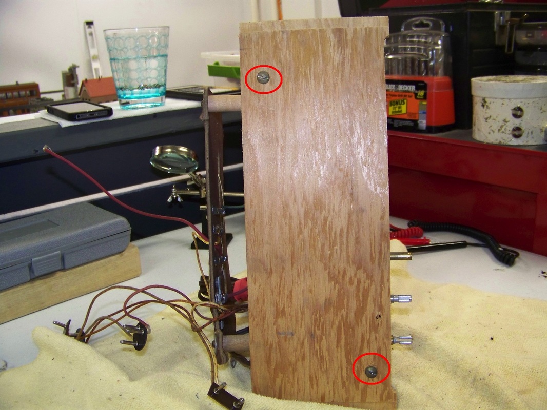
You will need to remove the wooden shelf in order to get at the components installed on the underside of the chassis. Two screws, circled in red, connect the shelf to the chassis.
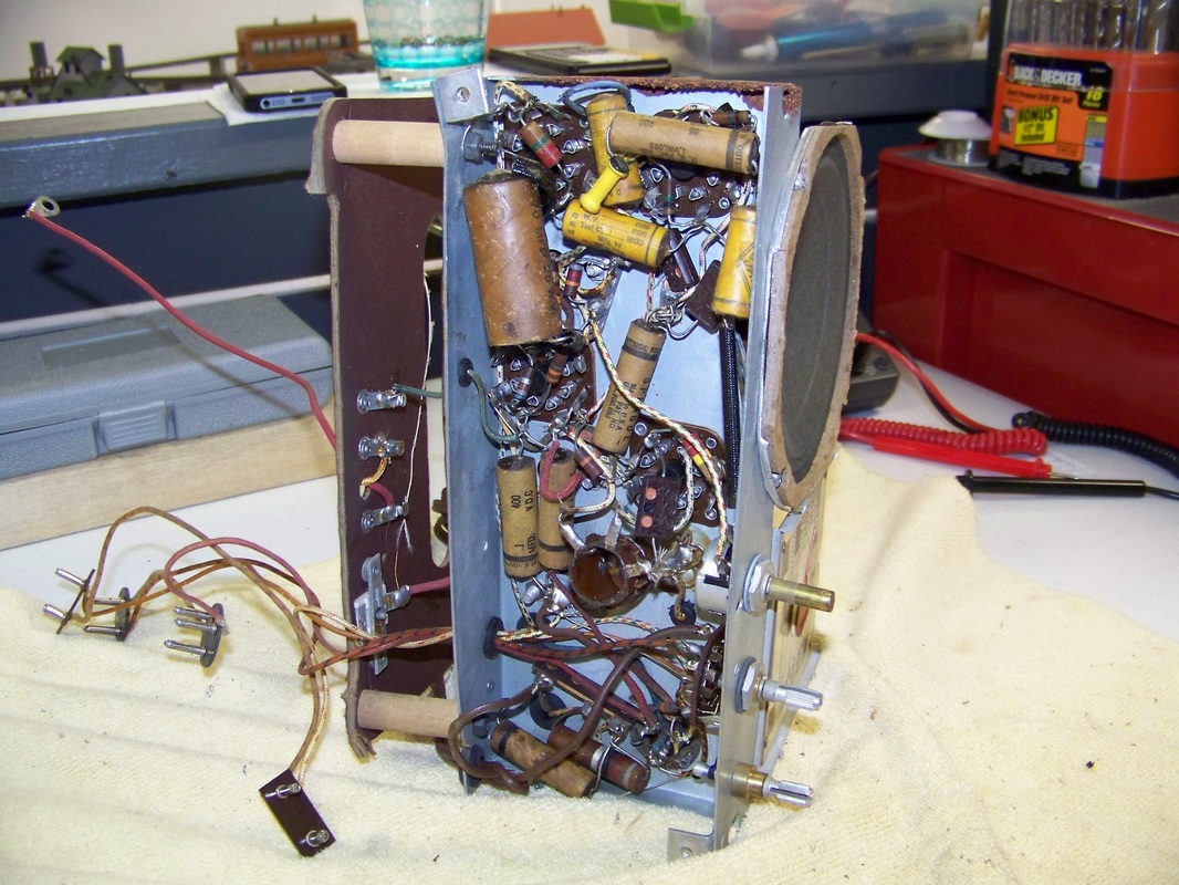
Here is a picture of the bottom of the chassis with the wooden shelf removed.
"Old Time Radios! Restoration and Repair" book on Amazon
I consult this book often during radio restoration. I grew up in the transistor and rectifier era and this book taught me a lot about vacuum tube and selium rectifier technology.
Step 2 Test Vacuum Tubes
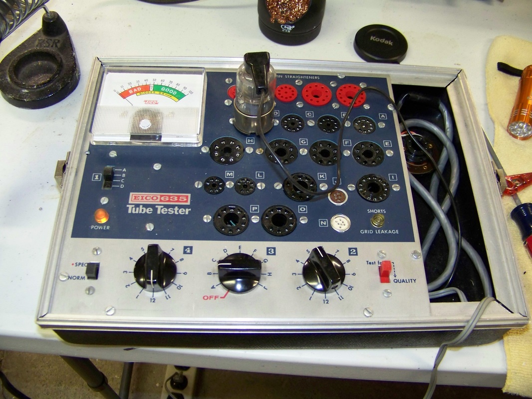
I use my trusty Eico 635 Tube Tester to check each vacuum tube in the Model 5020. Any defective or deficient vacuum tubes should be replaced before moving on to the next step.
Caution, Hot Chassis, Risk of Electrocution!
The Model 5020 connects one wire of the AC cord directly to the metal chassis when the power switch is in AC mode. This can mean that 120 Volt AC line voltage potential can be on the metal chassis, which can pose an electrocution risk, depending on how the non-polarized AC cord plug is plugged into the socket. You need to be mindful of this when operating the Model 5020 chassis outside of its cabinet! We will address this safety issue later in this blog with the installation of a polarized plug on the AC cord.
Step 3 Troubleshooting
You will need a schematic diagram of the Model 5020 to perform any more troubleshooting. I have provided a link below to said schematic.
There was no sound output when I initially plugged in the Model 5020 to 120 Volt AC line. I determined that part of the Multitap Candohm resistor that fed the tube filaments had an open. The resistance between the taps that was open was 1050 Ohms, according to the schematic. I used test leads with alligator connectors to wire in series four 250 Ohm wire- wound resistors then attached this resistor network across the taps with the broken resistance. SUCCESS! I could hear local AM Radio stations once the filaments heated up.
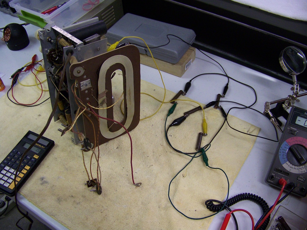
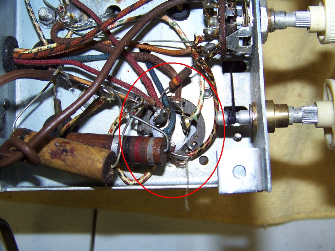
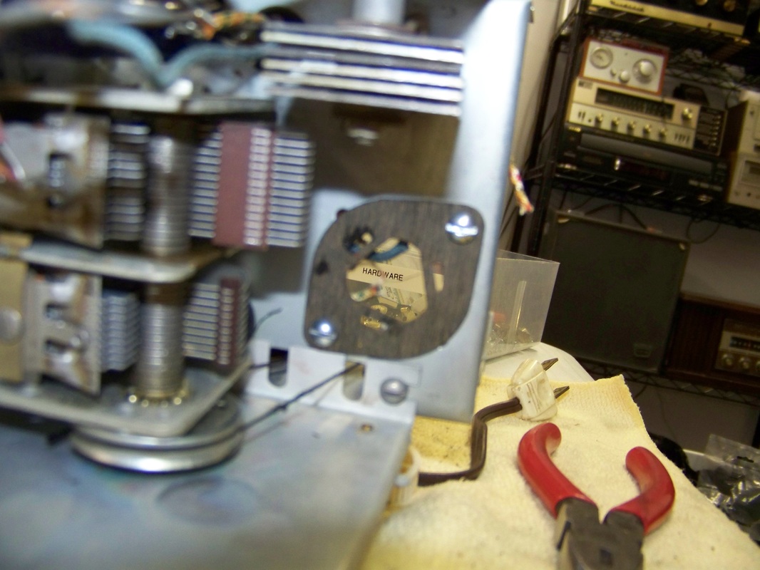
It was time for a more permanent fix. I soldered a 1000 Ohm wire-wound resistor across the two taps with the broken resistance. See area circled in the picture below.
Step 4 Electrolytic Capacitor Replacment
As electrolytic capacitors age, their electrolyte dries up causing their electrical capacity to drop and leakage current to increase. It is definitely a good idea to replace electrolytic capacitors that are over 60 years old!
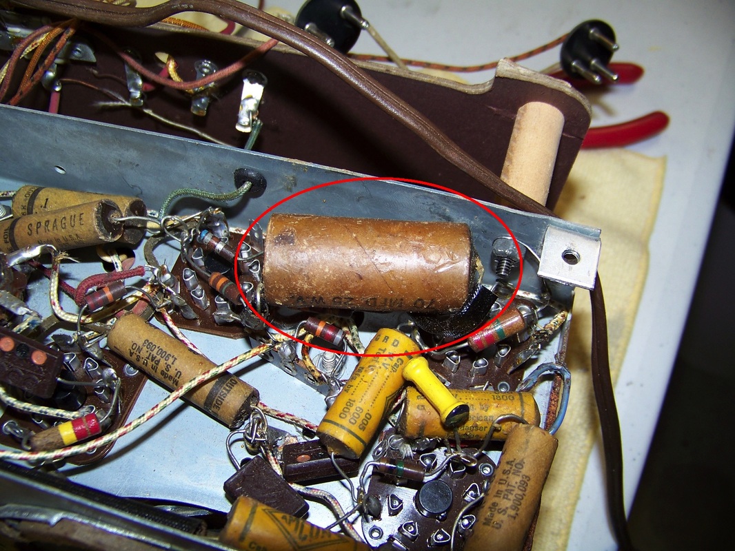
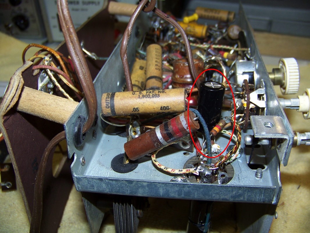
All electrolytic capacitors should be replaced with one of the same or slightly greater capacitance and working voltage rating. Here is the original 70uF 25 Volt capacitor.
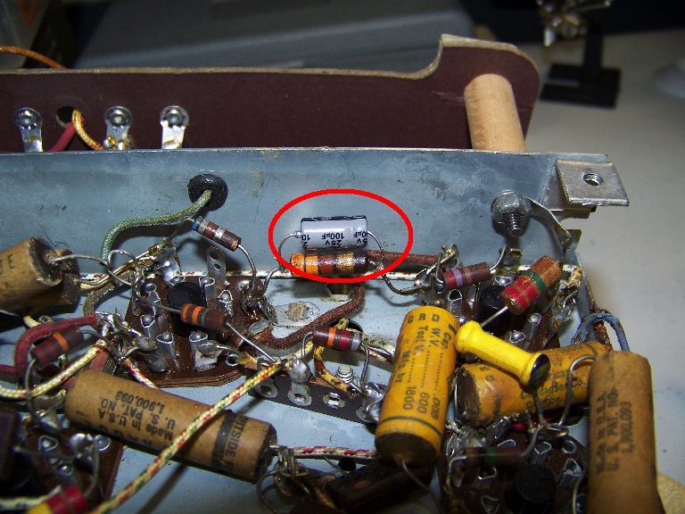
I replaced it with a 100uF 25 Volt electrolytic capacitor. I was able to piggy back the new electrolytic capacitor across a resistor due to its small size.
Step 4a Restoring the Multi-Section Capacitor
Multi-Section Capacitors, which were aluminum cans containing several discrete capacitors all connected to a common ground, were popular in the 1940s. They were used mostly in the power supply sections of vintage electronic devices. You can purchase replacement multi-section capacitors but they are expensive. I typically rebuild them by replacing their guts with inexpensive discrete capacitors of the same or slightly greater capacitance and working voltage.
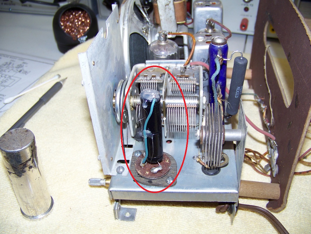
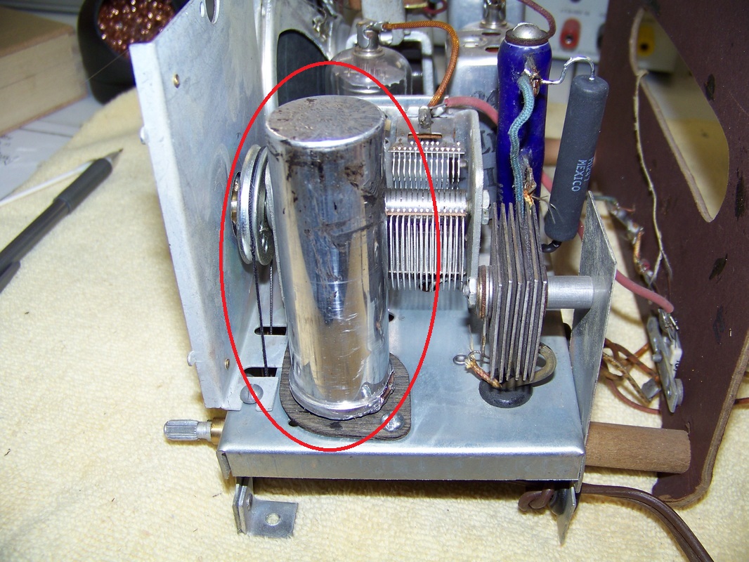
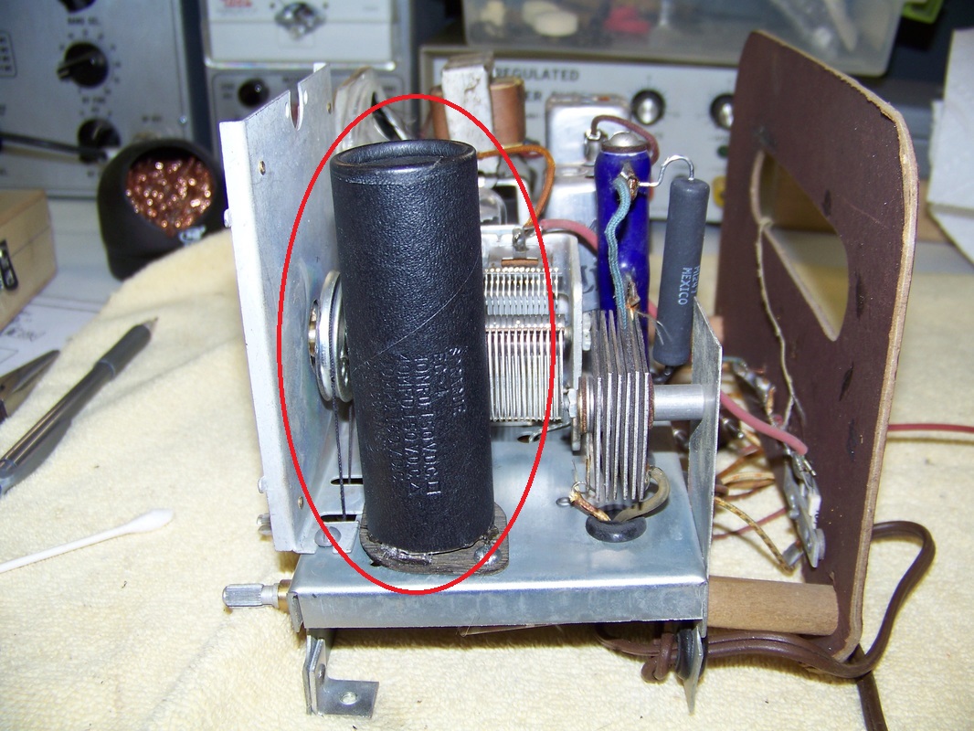
The Model 5020 employs a multi-section capacitor that contains three 40uF 150 Volt capacitors. The multi-section capacitor is circled in the picture below. 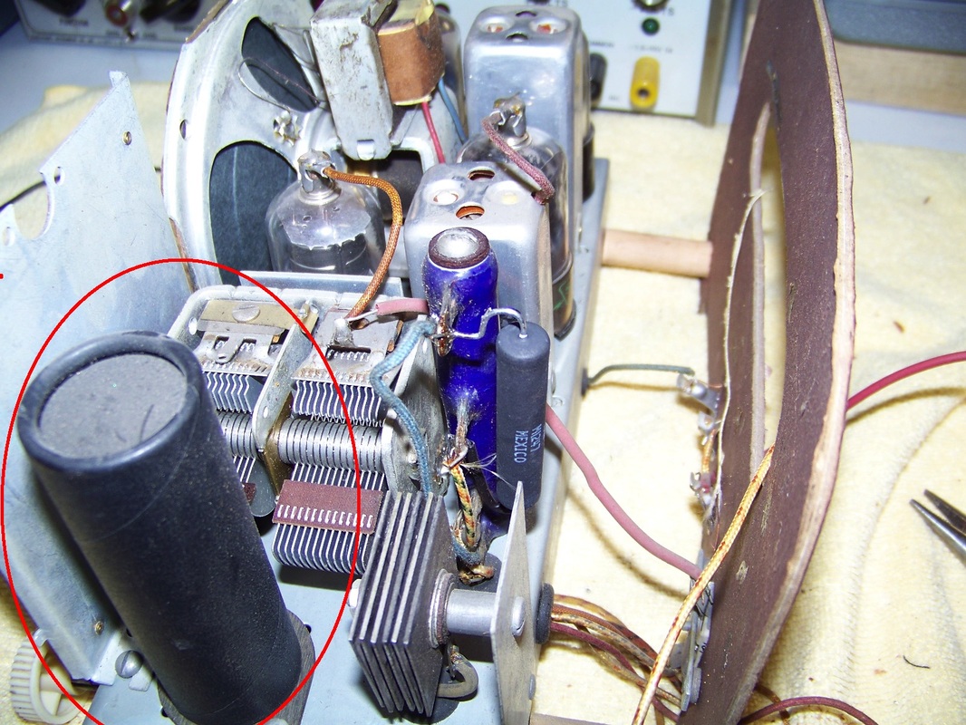
You must first un-solder all of the connections at the bottom of the multi-section capacitor before you can remove it from the chassis. You also need to drill out two rivets that hold the multi-section capacitor in place.
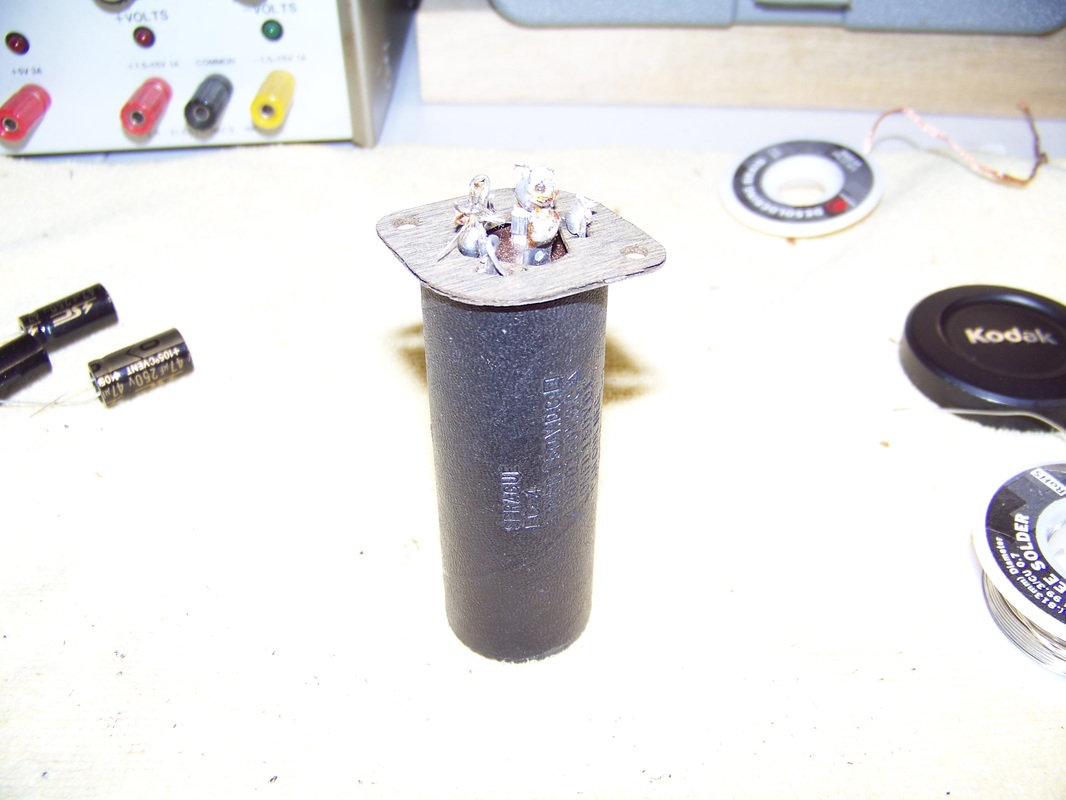
The multi-section capacitor removed from the chassis. The side of the cardboard cylinder indicates capacitance and working voltage of the internal capacitors.
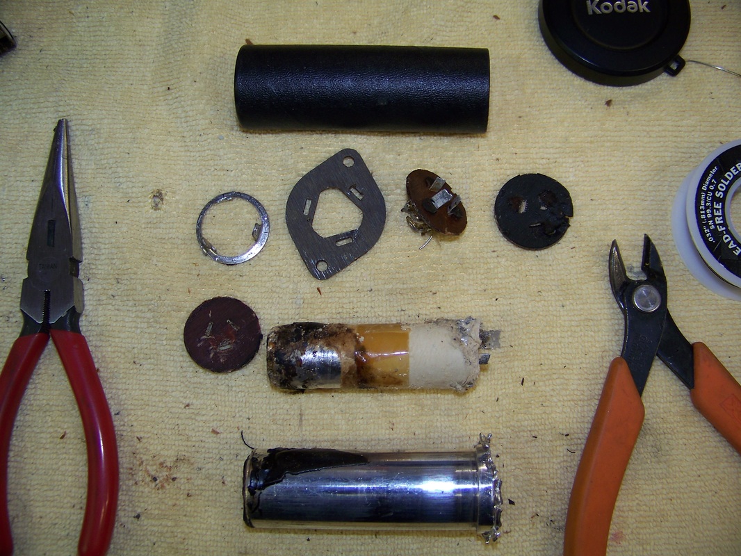
The guts of a multi-section capacitor. I use needle nose pliers to un-crimp the bottom of the aluminum can exposing the innards. I always wear nitrile gloves when working with the guts of capacitors as the electrolyte may cause skin irritation.
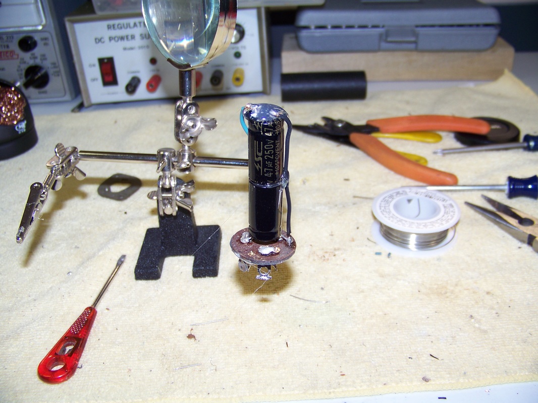
The new replacement capacitors soldered to the multi-section capacitor base. I use a dab of hot glue to secure them in place. Note: I am only able to hide two of the new 47uF 250 Volt capacitors in the "can", the third will be located under the chassis.
I use two machine screws to hold the phenolic wafer in place,
You must re-solder all of the connections to the base of the rebuilt multi-section capacitor after it is once again mounted to the chassis. The third 47uF 250Volt Electrolytic capacitor installed is circled in red below.
I use a Dremel with cutoff tool to remove the area from the base of the multi-section capacitor's aluminum can that I bent with needle-nose pliers.
Here is a picture of the installed newly reconstructed multi-section capacitor. Not very pretty at the moment.
I then slip the aluminum can of the multi-section capacitor over the new assembly. It is held in place with a couple dabs of hot glue at the bottom.
I then slide the cardboard cover over the aluminum can. No need for glue as the cover is a snug fit.
Step 4b Replacing the other Capacitors
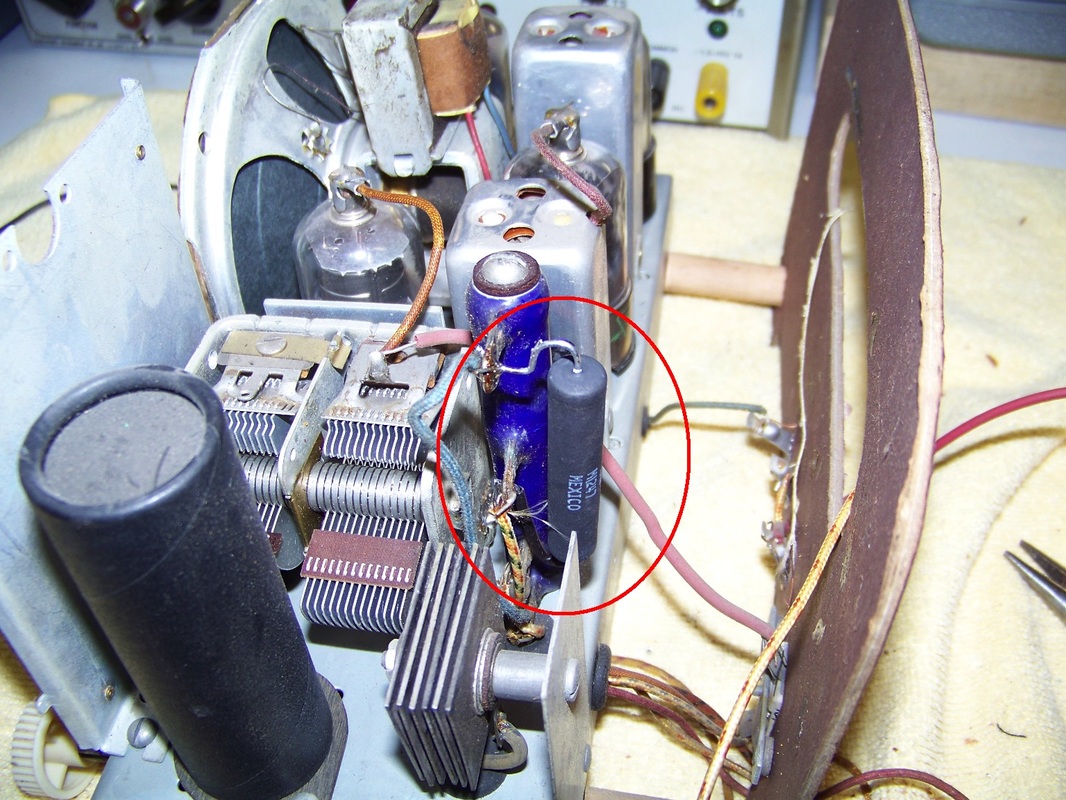
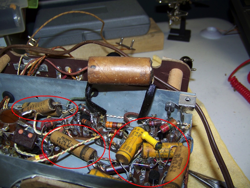
Paper/Wax capacitors, circled in red below, deteriorate with age due to acid in the paper.
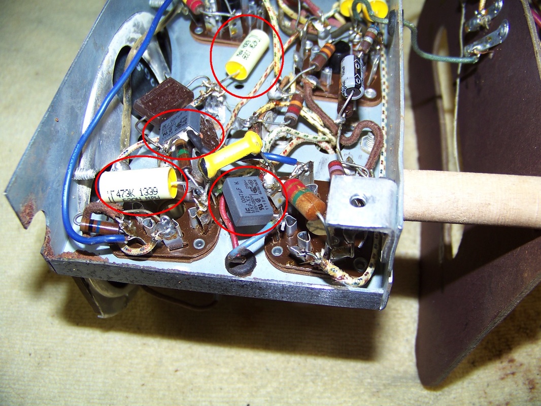
I decided to replace them with modern Metallized Polypropylene Capacitor of equivalent capacity and working voltage. These are the yellow and grey capacitors circled below.
Step 5 Cleaning and Lubrication
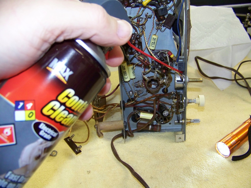
It is important to clean mechanical switch contacts and lubricate moving parts. Cleaning the chassis is not required but adds aesthetics to the Model 5020 restore.
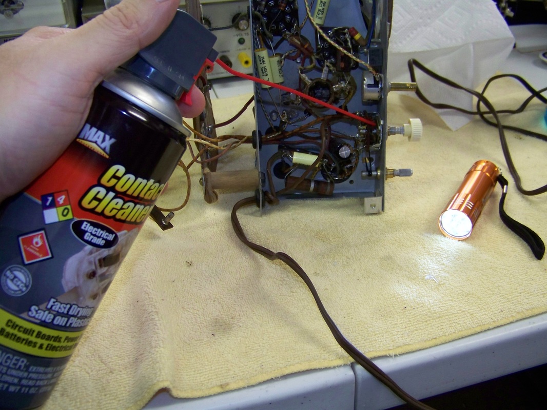
I spray contact cleaner into all switches then work the switch back and forth to clean the internal contacts.
I also spray contact cleaner into the innards of potentiometers and rheostats then work them through their full motion of movement.
Electrical contact cleaner on Amazon
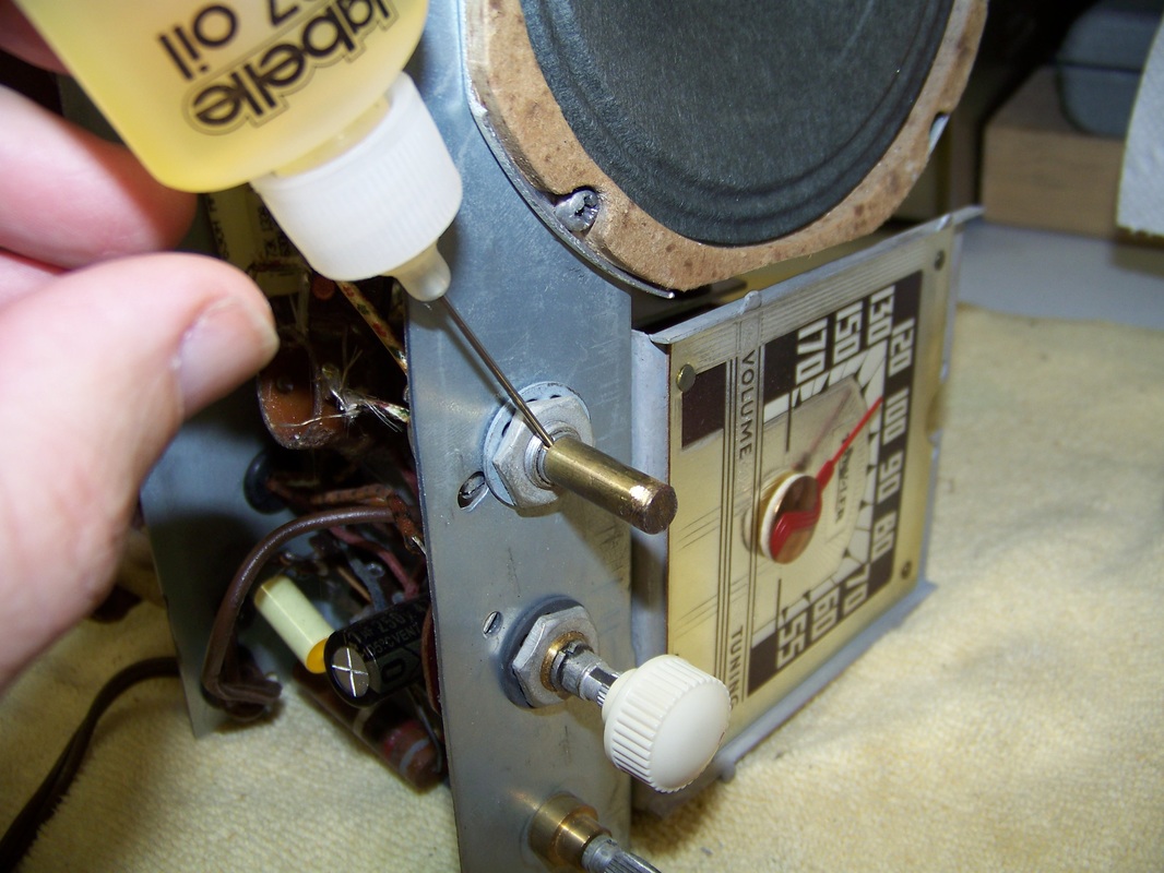
I use Labelle 107 model train oil to lubricate pulley shafts and other mechanisms. This oil will not harm plastics.
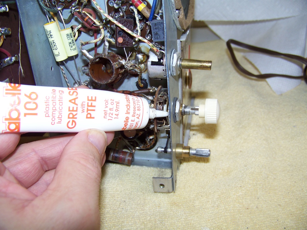
I use Labelle 106 model train grease to lubricate the bearings of the rotary switch. This grease will not harm plastics.
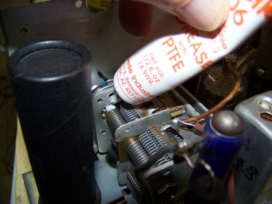
I also use Labelle 106 model train grease to lubricate the bearings of the variable capacitor.
Labelle lubricants on Amazon
I use Labelle oil and grease for my radio restoration projects. I already have these products around as I am also a model railroad enthusiast. These products will not harm plastic.
Step 6 Dealing with Chassis Rust
The Trav-ler Model 5020 I had recently acquired had a fair amount of rust on the edge of the chassis.
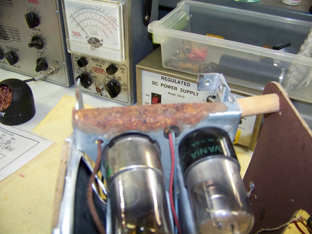
The rust was caused by a leaky 4.5 Volt Zinc-Carbon "A" battery left in the case by the previous owner.
The chemicals in this vintage Ray-O-Vac "A" battery had leaked through the cardboard case then attacked the steel chassis where it made contact.
The first step to chassis rust repair is to give yourself some room to work. I removed the vacuum tubes in the near proximity. I later decided to unsolder the red and blue wire that connects a AF (Audio Frequency) amplifier tube socket to the audio transformer then pull the wires out of the grommet. Then the grommet was removed as there was rust around the feed-through hole.
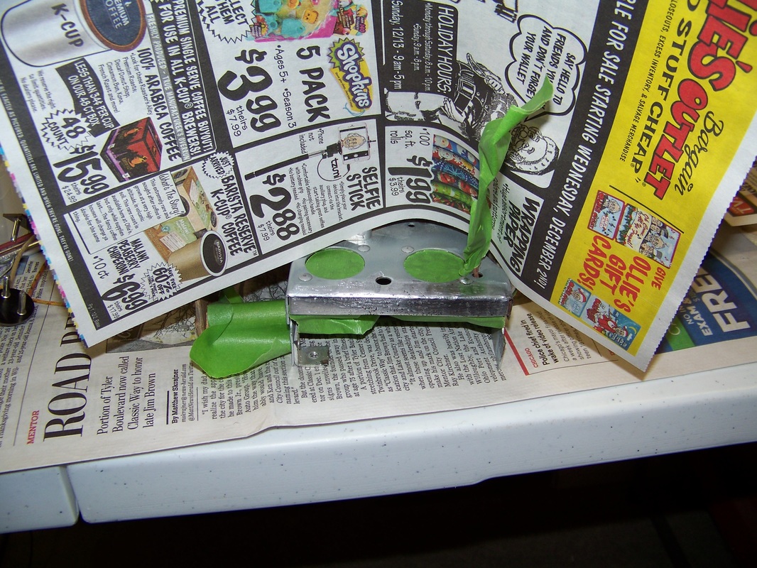
I started with a Dremel with a grinding wheel installed to remove as much of rust as possible. I then sanded the rusted area starting with coarse sandpaper finally finishing with a fine sandpaper. 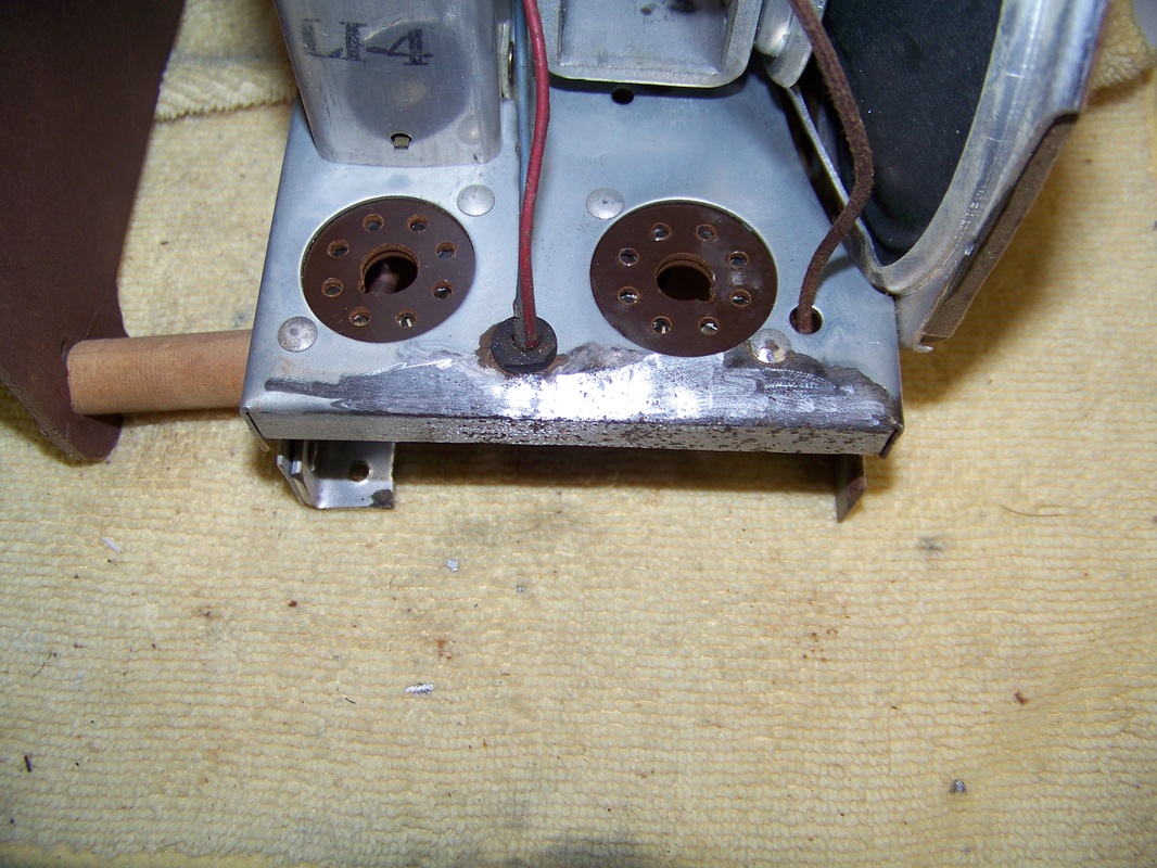
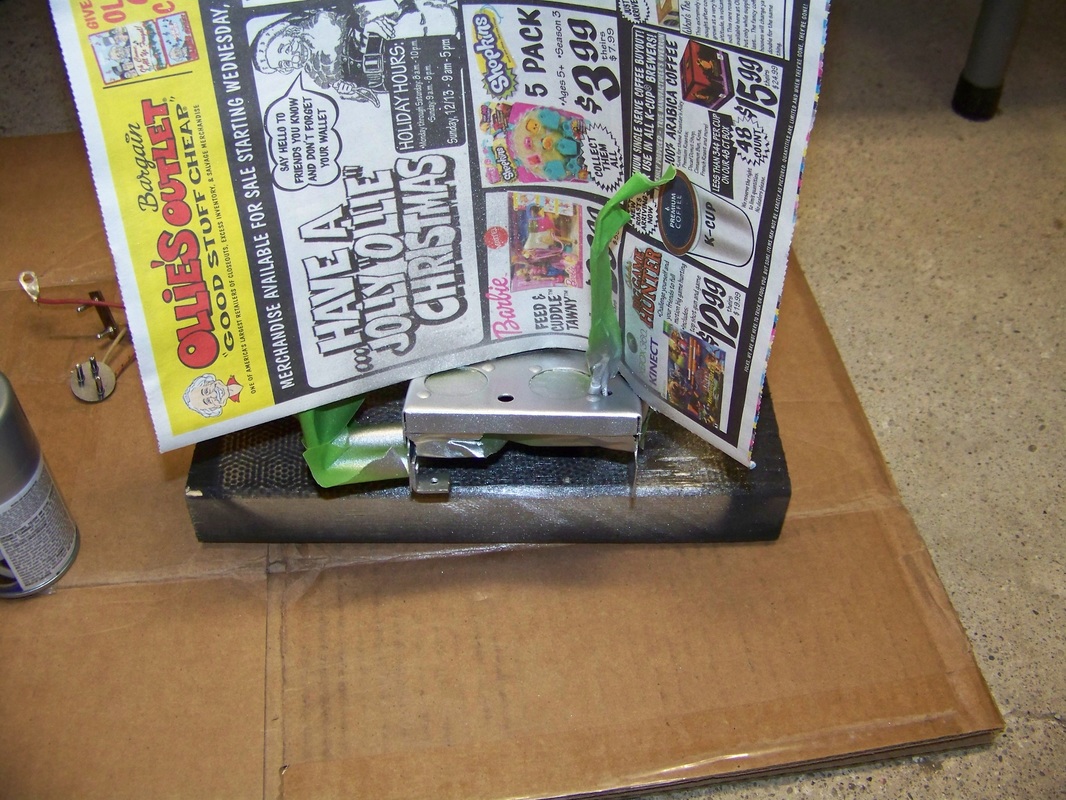
Below is a picture of the area masked off ready for paint. I used denatured alcohol to degrease the area before paint.
I use silver Dupli-Color automotive rim paint as it is the closet color I can find that matches the natural color of most chassis. Apply in light coats and feather it out so as to make a natural transition from the newly painted area to the chassis color.
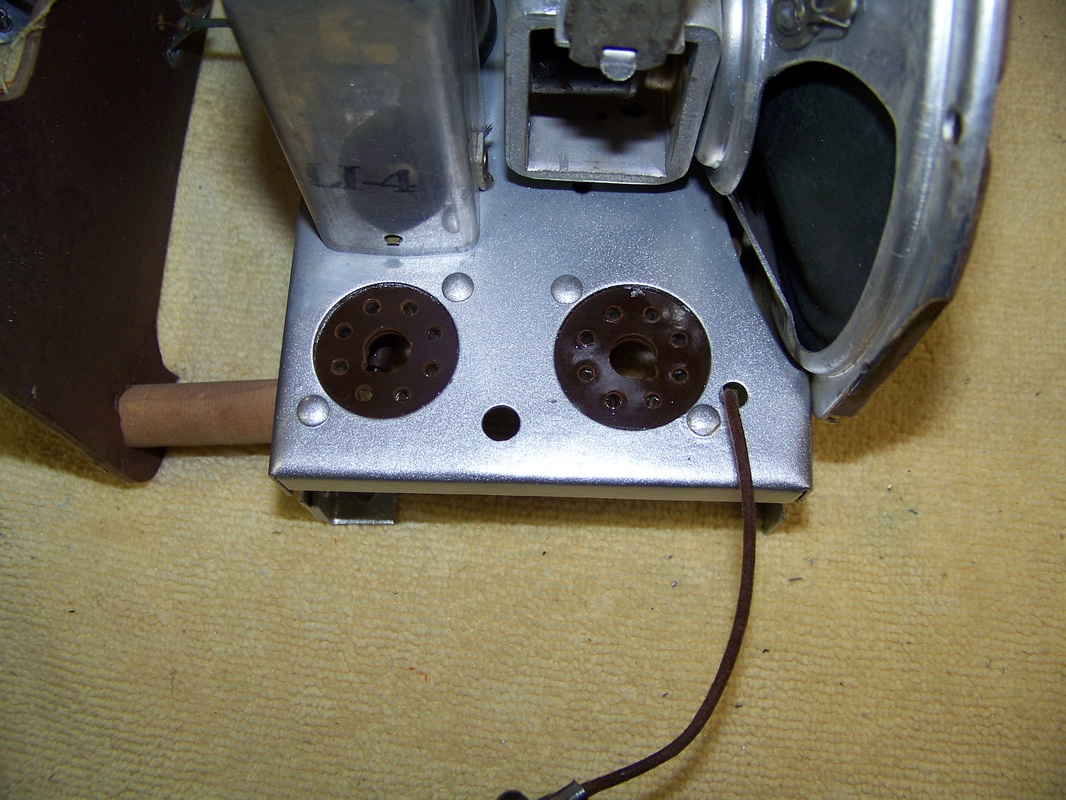
Repair job complete! Time to install a new grommet in the hole then thread the audio transformer through the installed grommet and solder to the AF (Audio Frequency) amplifier vacuum tube socket. The final step is to install the vacuum tubes into their respective sockets.
Duplicolor Rim Paint on Amazon
I use this paint to touch up places on the chassis that have rusted.
Step 7 Testing Under Battery Power
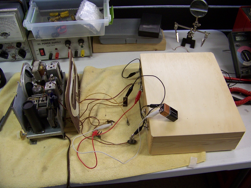
The Model 5020 was designed to run on 120 Volts AC Line Voltage or battery power which consists of Two "A" 4.5 Volt batteries connected in series to provide the required 9 Volts for the tube filaments. In addition, two "B" 45 Volt batteries are connected in series to provide the required 90 Volt plate voltage. I used my "battery box", the woodgrain case below, which contains ten 9 Volt batteries in series, to provide the "B" 90 Volts. In addition, I used a single 9 Volt battery for short duration to provide the "A" filament voltage. The model 5020 functioned as expected and I was able to detect several AM stations upon warm-up.
Step 8 Install Polarized Plug
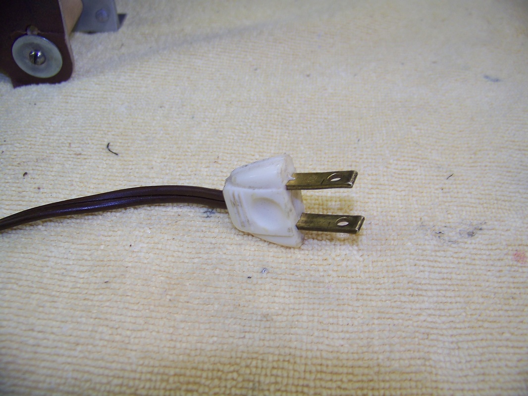
As mentioned earlier, an 120 Volt AC line voltage potential can be on the metal chassis, which can pose an electrocution risk, depending on how the non-polarized AC cord plug is plugged into the power outlet. Below is a picture of the original non-polarized plug.
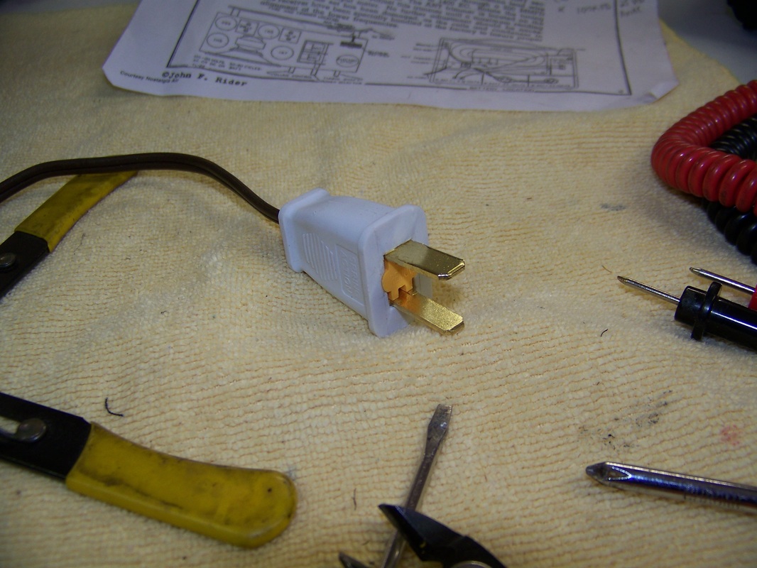
I replaced the plug with a polarized one that most closely matched the original. The wider blade should connect to the Model 5020 chassis as this is the Neutral connection. The thinner blade connects to Hot.
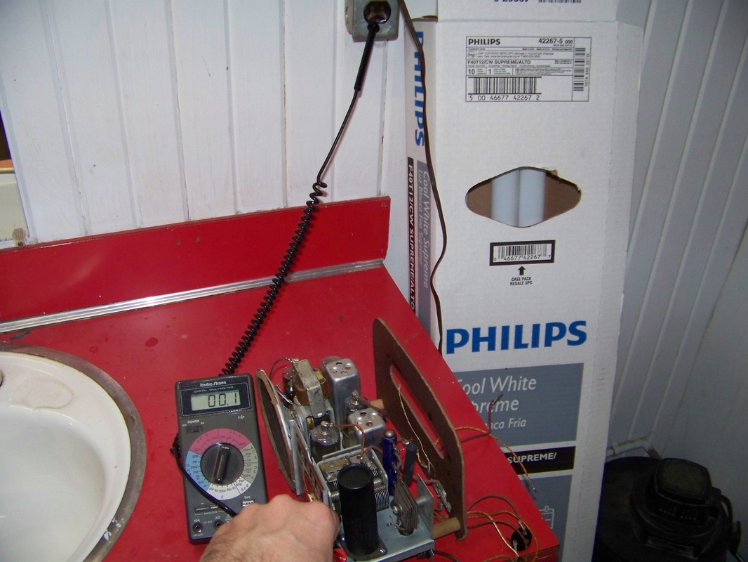
With the model 5020 plugged into an electrical socket, you should detect only a very low voltage (less than one Volt) AC between the ground connection on the wall socket and the chassis.
Step 9 Cabinet Restoration
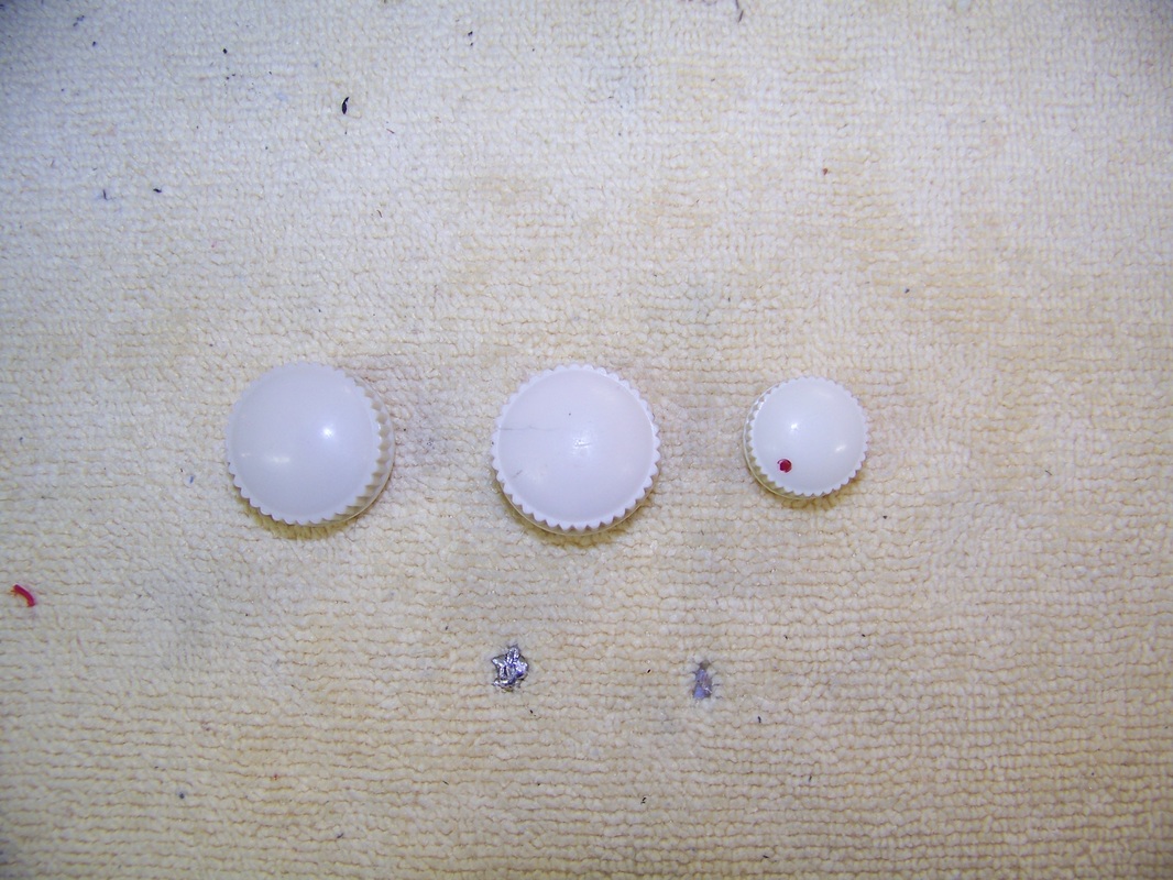
I use Meguiar's PlastX and a toothbrush to clean the knobs.
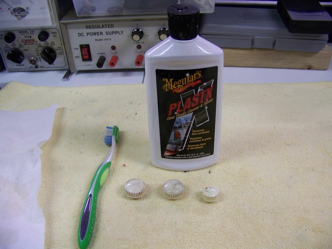
Here are the knobs after my cleaning job. Look ma, no cavities!
Meguiar's PlastX on Amazon
Meguiar's PlastX works great for cleaning up vintage knobs or to remove the "yellowing" of clear plastic lenses used over the tuning indicator. I also use other Meguire's automotive detailing products to bring back the luster of old radio cabinets.
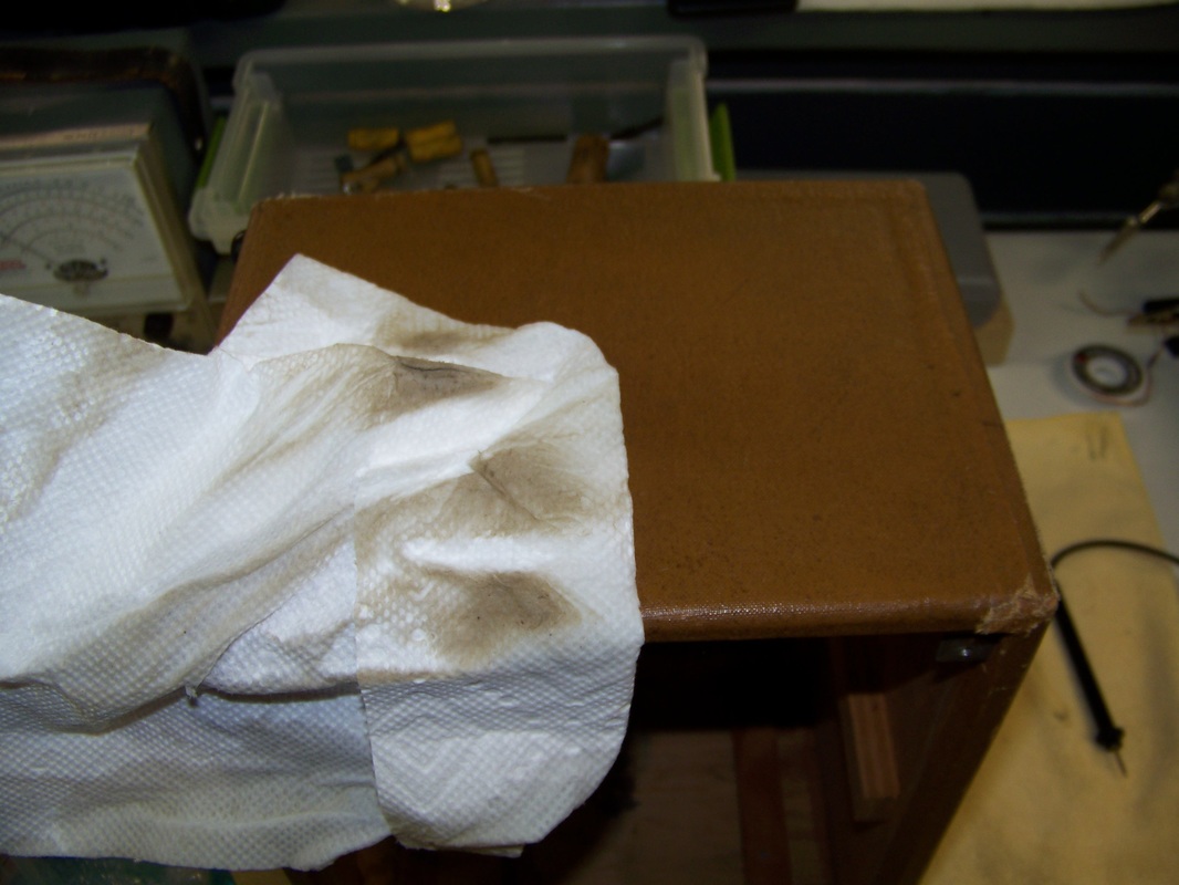
I used Windex and a paper towel to do the initial cleaning. Look at the dirt on my paper towel just from the initial rub down!
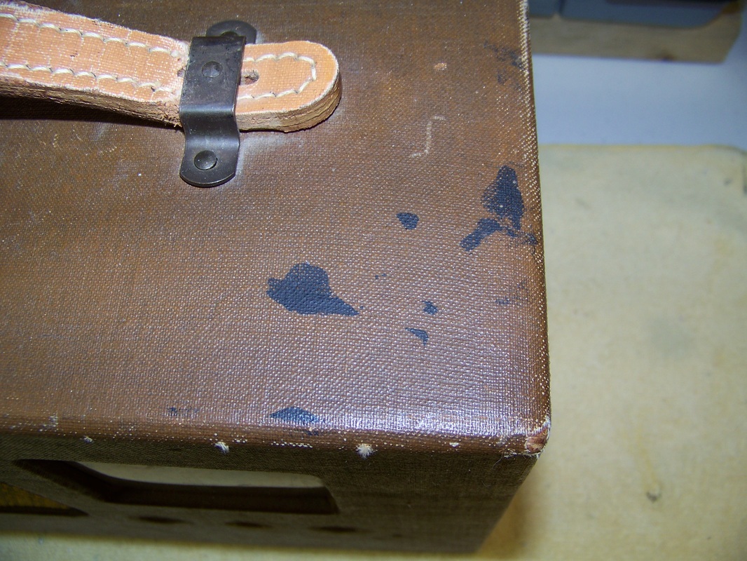
There are certain marks or stains that you just simply can't remove, like the dark black smudges in the picture below.
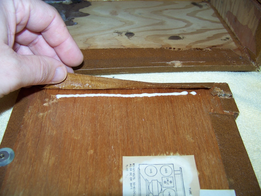
I use Elmer's wood glue to reattached the external cloth that has come loose during cleaning.
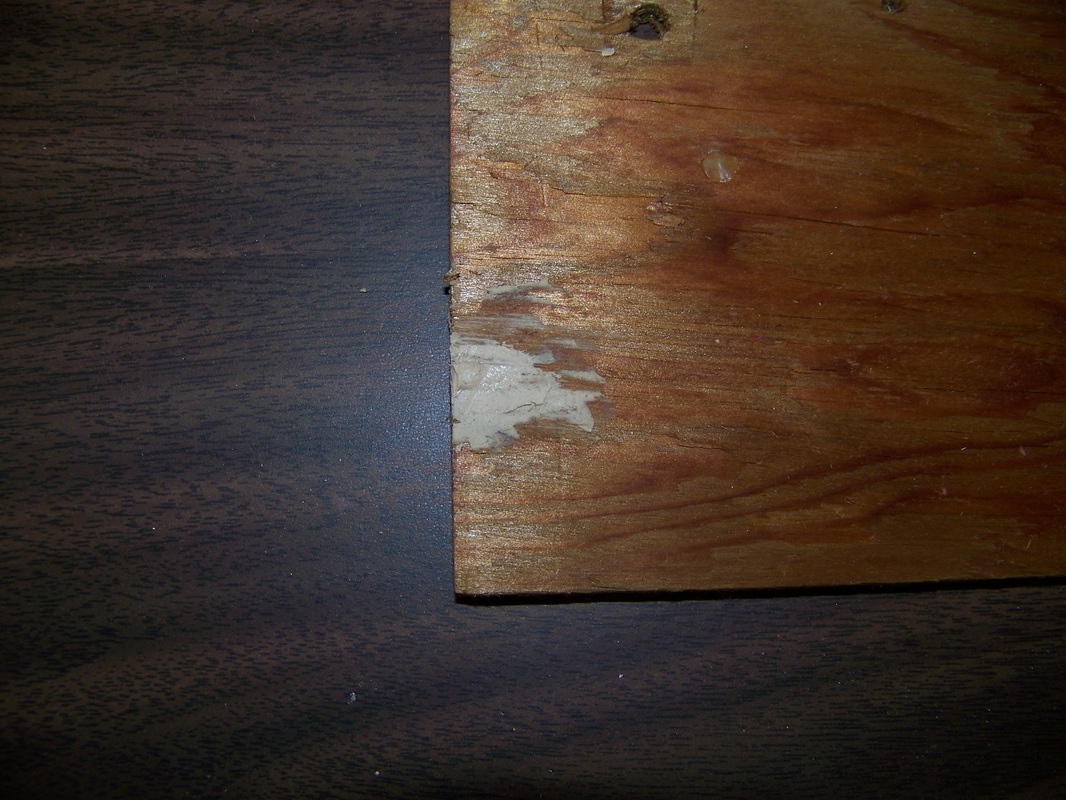
Elmer's wood putty also comes in handy to fix a spot, where the wood screw that holds the shelf in place, broke through the wood. Elmer's wood putty is "machinable" meaning you can drill a pilot hole in it in order to re-thread the screw.
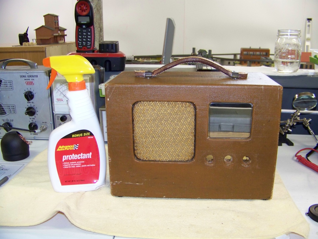
An automotive vinyl/leather protectant, similar to ArmorAll, really made the cabinet shine!
I use Old English furniture polish to clean/protect all internal wood surfaces.
Step 10 Chassis Install
Perform a final test of the chassis under 120 Volt AC power. Make sure you can still pickup AM radio stations. Follow the section "Step 1 Chassis Removal" in reverse order to reinstall the chassis back into the cabinet.
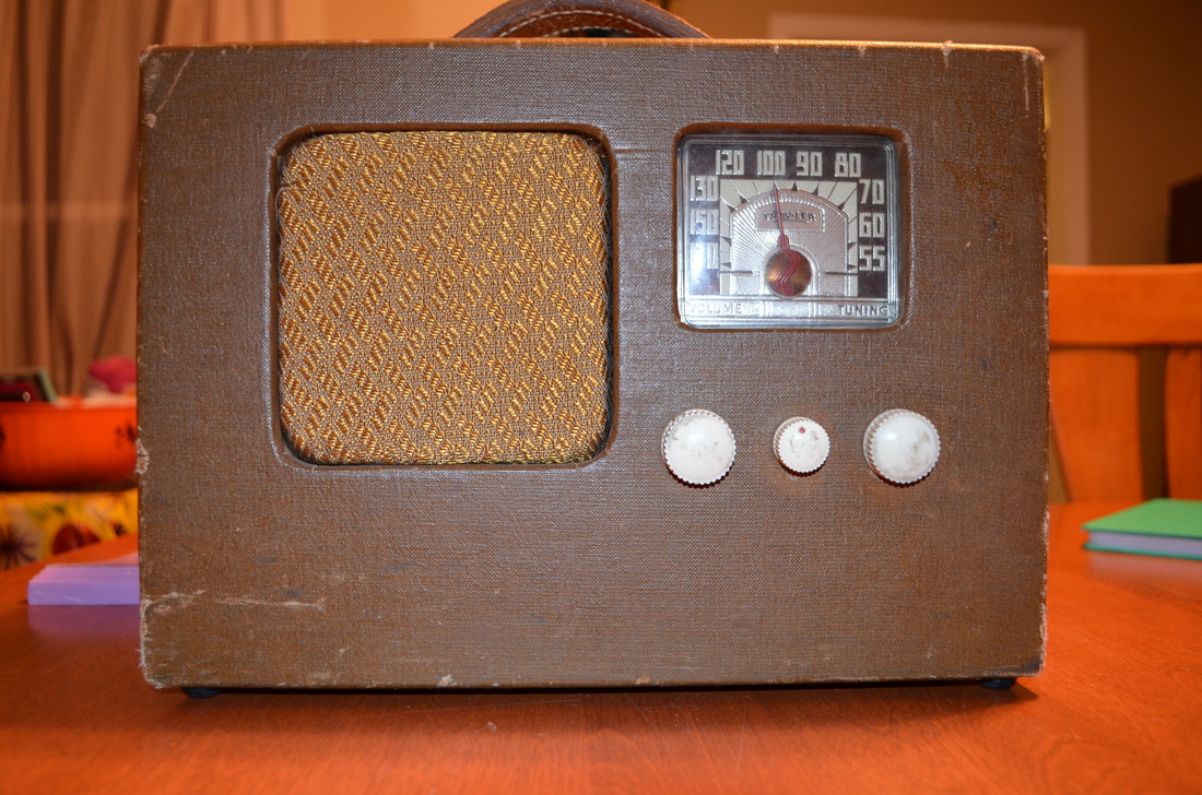
My newly restored Model 5020 in action!Conclusion
I spent many hours restoring this vintage 1947 Trav-ler Model 5020 back to its original specifications. It was a great project.
I wonder if the original owner of the Model 5020 ever thought that his/her radio would still be functioning well into the 21st Century? 
1 Comment
7/23/2019 10:12:17 pm
Having a portable radio is really important if you are traveling. When you start traveling, especially to the mountains, you will completely cut be cut off from civilizations. Those who do not want to be stuck during a possible calamity, then you will need to own a portable radio with you. Having a portable radio allows you to understand whether there is something serious happening to the other side. I really recommend buying one before you go and travel to the mountains. Leave a Reply. |

Who Writes This Blog?John is an IT professional from Cleveland, OH who enjoys amateur radio, ham radio, metal detecting, Archives
March 2021
Categories
All
Copyright © 2017
Radio Boat Anchor This page and all the pages on Radio Boat Anchor generate income based on an affiliate relationship with our partners including Zazzle, Amazon, and Google. Prices listed are subject to change without notice. |


 RSS Feed